Dipole length chart for every HF band
Cut three percent long, hang it at final height, then trim.
The short answer
A half wave dipole in feet is approximately 468 divided by the frequency in megahertz, so a 40 metre dipole at 7.15 MHz is 65 ft 5 in overall, with each leg 32 ft 9 in. Cut three percent long and trim after measuring at final height, because height and nearby objects both shift resonance downward.
- Half wave formula
- 468 / f in MHz
- Quarter wave formula
- 234 / f in MHz
- Start long by
- 3 percent
- Trim rule
- 1 percent length, 1 percent frequency
- Measure at
- Final height
- Insulated wire
- Cut 2 to 4 percent shorter
These are the cut lengths for the three antenna types most people build: a centre fed half wave dipole, a quarter wave vertical, and an end fed half wave. The formula behind all of them is the same, and the figures already include the velocity factor of wire near ground, which is why the constant is 468 rather than 492.
Treat every number here as a starting point. Height above ground, wire insulation, the angle of an inverted V and anything metal nearby all shift resonance, almost always downward. Cut long, hang it, measure, then trim.
Lengths by band
Cut lengths
Half wave, dipole leg and quarter wave by band
| Band and frequency | Half wave total | Each dipole leg | Quarter wave |
|---|---|---|---|
| 160 m, 1.900 MHz | 246 ft 4 in | 123 ft 2 in | 123 ft 2 in |
| 80 m, 3.600 MHz | 130 ft 0 in | 65 ft 0 in | 65 ft 0 in |
| 80 m, 3.800 MHz | 123 ft 2 in | 61 ft 7 in | 61 ft 7 in |
| 60 m, 5.357 MHz | 87 ft 4 in | 43 ft 8 in | 43 ft 8 in |
| 40 m, 7.050 MHz | 66 ft 5 in | 33 ft 2 in | 33 ft 2 in |
| 40 m, 7.200 MHz | 65 ft 0 in | 32 ft 6 in | 32 ft 6 in |
| 30 m, 10.125 MHz | 46 ft 3 in | 23 ft 1 in | 23 ft 1 in |
| 20 m, 14.100 MHz | 33 ft 2 in | 16 ft 7 in | 16 ft 7 in |
| 20 m, 14.250 MHz | 32 ft 10 in | 16 ft 5 in | 16 ft 5 in |
| 17 m, 18.110 MHz | 25 ft 10 in | 12 ft 11 in | 12 ft 11 in |
| 15 m, 21.100 MHz | 22 ft 2 in | 11 ft 1 in | 11 ft 1 in |
| 15 m, 21.300 MHz | 22 ft 0 in | 11 ft 0 in | 11 ft 0 in |
| 12 m, 24.940 MHz | 18 ft 9 in | 9 ft 5 in | 9 ft 5 in |
| 10 m, 28.400 MHz | 16 ft 6 in | 8 ft 3 in | 8 ft 3 in |
| 10 m, 29.000 MHz | 16 ft 2 in | 8 ft 1 in | 8 ft 1 in |
| 6 m, 50.150 MHz | 9 ft 4 in | 4 ft 8 in | 4 ft 8 in |
| 2 m, 146.000 MHz | 3 ft 2 in | 1 ft 7 in | 1 ft 7 in |
For any frequency not listed, use the dipole length calculator or the quarter wave vertical calculator. For an end fed, the wire is the half wave figure and the end fed half wave calculator covers the counterpoise as well.
End fed half wave lengths
An end fed half wave uses the same total length as a dipole but is fed at one end through a 49 to 1 transformer. Because it is close to resonant on even harmonics, one wire covers several bands.
End fed
Multiband coverage from one wire
| Design band | Wire length | Also covers | Counterpoise |
|---|---|---|---|
| 80 m | About 130 ft | 40, 20, 15, 10 m | About 6 ft 6 in |
| 40 m | About 66 ft | 20, 15, 10 m | About 3 ft 3 in |
| 20 m | About 33 ft | 10 m | About 1 ft 8 in |
| 30 m | About 46 ft | 15 m | About 2 ft 4 in |
The counterpoise figure is roughly 0.05 wavelengths on the design band. It is not optional. Without it the antenna uses the outside of your coax braid as the counterpoise, which puts RF in the shack. Fit a choke as well.
Trimming
Trim amounts
Wire to remove to move resonance up by a given amount
| Band | Half wave | Up 50 kHz | Up 100 kHz | Up 200 kHz |
|---|---|---|---|---|
| 80 m at 3.7 MHz | 126 ft 6 in | 20 in | 41 in | 82 in |
| 40 m at 7.1 MHz | 65 ft 11 in | 5.5 in | 11 in | 22 in |
| 30 m at 10.1 MHz | 46 ft 4 in | 2.8 in | 5.5 in | 11 in |
| 20 m at 14.15 MHz | 33 ft 1 in | 1.4 in | 2.8 in | 5.6 in |
| 17 m at 18.1 MHz | 25 ft 10 in | 0.9 in | 1.7 in | 3.4 in |
| 15 m at 21.2 MHz | 22 ft 1 in | 0.6 in | 1.3 in | 2.5 in |
| 10 m at 28.4 MHz | 16 ft 6 in | 0.4 in | 0.7 in | 1.4 in |
On a centre fed dipole, split the figure across both legs. On an end fed, take the whole amount from the far end. Take half your calculated cut on the first pass, because you cannot easily put wire back. Full method in how to tune an antenna with an SWR meter.
The fastest way to find where the antenna actually resonates is a swept measurement rather than trial transmissions; the best antenna analyzers page compares the NanoVNA H4 and the RigExpert AA-650 Zoom for exactly this job.
What shifts these numbers
- Height above ground. A dipole at a quarter wavelength resonates lower than the same dipole at half a wavelength. Always measure at final height.
- Insulated wire. Insulation slows the wave, so an insulated wire is 2 to 4 percent shorter than a bare one for the same resonance.
- Inverted V angle. Drooping the ends lowers resonance and lowers the feedpoint impedance. A 120 degree included angle is a common compromise.
- Nearby metal. Gutters, fences, mast sections and other antennas all couple capacitively and pull resonance down.
- End effect. Already accounted for in the 468 constant, which is why the constant is not the free space 492.
- Wire diameter. Thicker conductors are slightly shorter for the same resonance and have wider bandwidth, which is why fat elements are used on beams.
What to build it from
Wire, rope and hardware
The whole antenna is inexpensive. The rope is what decides how long it lasts.
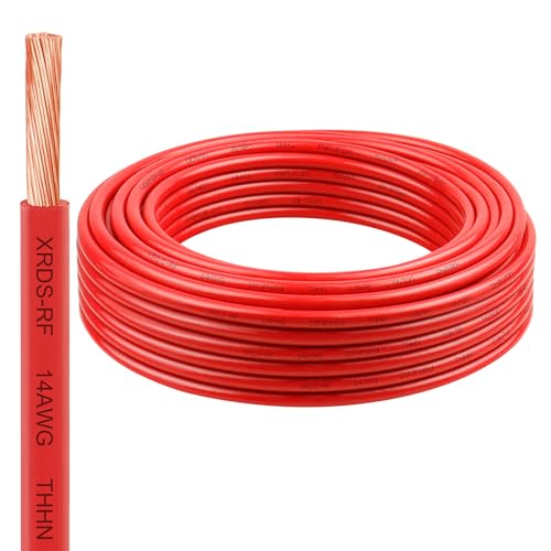
XRDS-RF
XRDS-RF 14 AWG stranded copper wire, 25 ft
Stranded insulated wire that survives being pulled into a tree and left there for years.
Check priceUnder $25

Paladin
Paladin 14 AWG stranded copper wire, 500 ft
A larger spool for building several antennas or a radial field.
Check priceUnder $100

Quality Nylon Rope
QNR 3/16 in polyester antenna rope, 500 ft
UV-stable, low-stretch support rope. The single component that decides whether the antenna survives a season.
Check priceUnder $50

Redman
Nylon dog bone antenna insulators, 10-pack
End insulators so the high-voltage wire tips terminate into rope rather than into a branch.
Check priceUnder $50
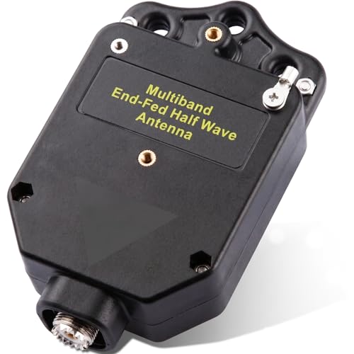
GOOZEEZOO
GOOZEEZOO 150 W end fed antenna transformer
A 49 to 1 transformer for building an end fed from your own wire.
Check priceUnder $50

Fair-Rite type 31
FT-240-31 ferrite toroid core
A ferrite core for the common mode choke that every wire antenna installation needs.
Check priceUnder $25

Forester
Forester arborist throw line kit
Getting the support line over a branch, which is the actual hard part.
Check priceUnder $25

AURSINC
NanoVNA H4 vector network analyzer
Shows where the antenna is resonant, which turns four trips outside into one.
Check priceUnder $100
Common questions
Questions people ask about this
How long is a 40 metre dipole?
About 65 ft 5 in overall at 7.15 MHz, which is 32 ft 9 in per leg. That figure comes from 468 divided by the frequency in megahertz and already includes the end effect that makes a real wire shorter than a free space half wave. Cut about three percent long, hang it at final height, measure the resonance and then trim.
Why is the constant 468 rather than 492?
A half wavelength in free space in feet is 492 divided by the frequency in megahertz. A real wire near ground is electrically longer than its physical length because of end effect and the velocity factor of a conductor with finite diameter, so the physical length needed for resonance is shorter. The 468 constant absorbs that correction and works well for typical amateur wire.
Do I cut the same length for insulated and bare wire?
No. Insulation slows the wave slightly, so an insulated wire resonates lower than a bare wire of the same length and needs to be about two to four percent shorter. The practical approach is identical either way: cut long, measure the actual resonance at final height, and trim, since the exact factor depends on the specific insulation.
Does it matter if my dipole is an inverted V?
It works well and it changes the numbers slightly. Drooping the ends lowers the resonant frequency and lowers the feedpoint impedance, so an inverted V typically needs to be a little shorter than a flat top and often shows a better match to 50 ohm coax. It also needs only one high support point, which is why so many people build them.
How do I know if my antenna is too long or too short?
Sweep it with an antenna analyser and find the frequency of minimum SWR. If that frequency is below the band you want, the antenna is too long and needs trimming. If it is above, the antenna is too short and needs wire added. A single SWR reading at one frequency cannot tell you which, which is why an analyser is the tool that saves trips outside.
Keep going
Related on this site
Disclaimer Researched guidance for planning purposes, not professional engineering, electrical or legal advice. Antenna work, RF exposure, mast and tower work, grounding and battery handling all carry real risk that depends on your specific site and installation. Verify anything safety-critical against current FCC rules, the National Electrical Code and the manufacturer's own documentation, and hire a professional where the job calls for one. We research equipment from published specifications, regulatory documents and verified owner reviews rather than claiming hands-on testing we have not done.