Reading SWR and fixing a bad match
A number on a meter is a symptom. This is how to work out what it is a symptom of.
The short answer
SWR below 2 to 1 is fine and needs no action. A reading that is high on every band points at the feedline or connectors, a reading that is high on one band points at the antenna length, and a reading that changes when you touch the equipment is common mode current rather than a match problem at all.
- Acceptable SWR
- Under 2:1
- Power reflected at 2:1
- 11 percent
- Power reflected at 3:1
- 25 percent
- Loss at 2:1, good coax
- Under 0.5 dB
- Most common cause
- Connector or water
- Best diagnostic tool
- Antenna analyser
Standing wave ratio is the most watched and least understood number in the shack. It gets treated as a quality score for the antenna, which it is not, and a low reading gets treated as proof everything is fine, which it also is not. A dummy load reads a perfect 1 to 1 and radiates nothing.
What SWR actually measures is how much of the power you send down the feedline comes back. That is genuinely useful information, and it is useful mainly as a diagnostic: the pattern of readings across frequency tells you what is wrong far more precisely than any single number.
This page covers what the reading means, what is worth worrying about, and a diagnostic order that finds the fault.
What the number means
A perfectly matched 50 ohm load absorbs everything you send and reflects nothing, which is 1 to 1. Any mismatch reflects some fraction back toward the transmitter, and the ratio between the peak and trough of the resulting standing wave is what the meter reports.
SWR translated
What each reading actually costs
| SWR | Power reflected | Loss if perfectly matched | Verdict |
|---|---|---|---|
| 1.0:1 | 0 percent | 0 dB | Perfect, and slightly suspicious on a real antenna |
| 1.5:1 | 4 percent | 0.18 dB | Excellent, stop adjusting |
| 2.0:1 | 11 percent | 0.51 dB | Fine. Inaudible at the far end |
| 2.5:1 | 18 percent | 0.88 dB | Acceptable, most radios still run full power |
| 3.0:1 | 25 percent | 1.25 dB | Radio starts folding back, use a tuner |
| 5.0:1 | 44 percent | 2.55 dB | Something is wrong, investigate |
| 10:1 | 67 percent | 4.81 dB | A fault, not a match issue |
The loss column assumes lossless feedline and shows only the mismatch penalty. Real feedline adds its own loss, and that loss is what turns a modest mismatch into a real problem at VHF. The SWR calculator covers reflected power and return loss for any reading.
The diagnostic order
Work through these in sequence. The order is deliberate, because it eliminates the cheap and common causes before the expensive and rare ones.
Finding the actual fault
- 1
Is it high on every band, or one?
High everywhere points at the feedline, a connector, or a short. High on one band with others fine points at antenna length or a trap. This single question eliminates half the possibilities.
- 2
Substitute a dummy load at the radio
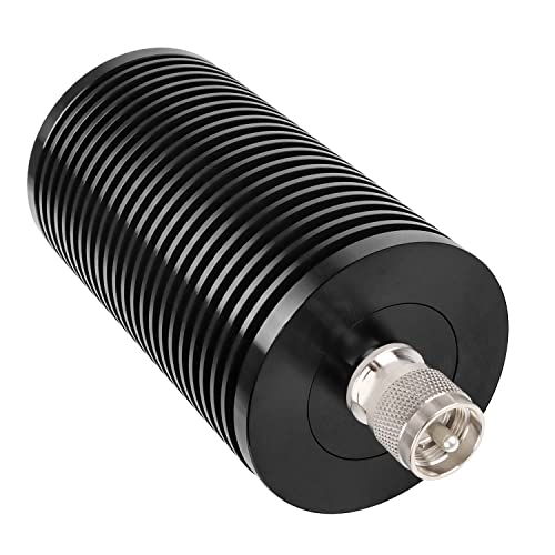
Connect an XRDS-RF 100 W dummy load, 50 ohm directly to the radio. If SWR is now 1 to 1, the radio and the meter are fine and the problem is downstream. If it is not, the meter or the radio is at fault.
- 3
Move the dummy load to the far end of the coax
With the load at the antenna end, the reading at the shack should be close to 1 to 1, slightly better than 1 to 1 in fact because cable loss masks reflections. A high reading here means the feedline or a connector.
- 4
Inspect every connector, especially outdoors
Water in a PL-259 is the single most common cause of a mysterious rise in SWR. Look for green corrosion, a loose braid crimp, and a centre pin that has pushed back. See how to install PL-259 connectors.
- 5
Sweep the antenna with an analyser
A NanoVNA H4 vector network analyzer or a RigExpert AA-650 Zoom antenna analyzer shows resonance across the whole band in seconds. Resonance below the band means the antenna is too long, above it means too short. That is a far more useful answer than a single number.
- 6
Check for common mode current
If the reading changes when you touch the radio, move the coax or key up with your hand near the case, RF is on the outside of the braid. No amount of trimming fixes it. Fit a choke.
Reading the sweep
An analyser turns SWR from a number into a shape, and the shape tells you what to change.
- A clean dip, below the band
- The antenna is too long. Trim both ends equally on a dipole, or the single wire on an end fed. Roughly, one percent of length shifts resonance about one percent in frequency.
- A clean dip, above the band
- Too short. Add wire, or add a short length with an alligator clip to confirm before you commit to soldering.
- A shallow dip that never reaches a low SWR
- The feedpoint impedance is not near 50 ohms even at resonance. Usually a height issue on a dipole, or a missing counterpoise or radial field on a vertical or end fed.
- No dip at all, flat and high everywhere
- An open or a short. A broken element, a disconnected radial, or a connector that has failed. Check continuity.
- A flat and low reading everywhere, on every band
- Suspicious. Very lossy feedline masks reflections and produces a beautiful reading from an antenna that is not working. Check the cable loss against what it should be.
- A dip that moves when it rains
- Water. Either into a connector or into a trap. This is normal for a small shift and a fault for a large one.
Fixing what you find
- Wrong length: trim or extend. Cut long and trim in small steps, because you cannot put wire back easily. On a dipole, take the same amount from both legs.
- Water in a connector: replace the connector, do not dry it. Then weatherproof properly with Self-amalgamating rubber splicing tape and an over-wrap, or Hand-moldable sealant tape.
- Corroded or badly soldered PL-259: replace it. A PL-259 solder connectors with reducers, 6-pack costs less than an evening of chasing the fault.
- Missing counterpoise on an end fed: add a wire roughly 0.05 wavelengths long at the transformer, and fit a choke behind it.
- Insufficient radials on a vertical: more radials, laid on the ground, is the answer. See the radial planning calculator.
- Common mode current: a choke at the feedpoint. A FT-240-31 ferrite toroid core core with the coax wound through it, or a commercial Balun Designs 1171 1:1 current balunnot on amazon.
- Genuinely wide bandwidth needed: a tuner is the honest answer. See antenna tuner basics.
Measuring it properly
Tools that answer the question
A meter tells you there is a problem. An analyser tells you what it is.

AURSINC
NanoVNA H4 vector network analyzer
A full vector network analyser for the price of a meter. Sweeps the whole band, shows resistance and reactance, and finds the fault rather than reporting it.
Check priceUnder $100

RigExpert
RigExpert AA-650 Zoom antenna analyzer
A rugged handheld analyser with a real display and no computer needed. The tool you take up a mast.
Check priceUnder $1,000

Surecom
Surecom SW-102 digital VHF/UHF SWR meter
Inline digital power and SWR for confirming what the radio is actually doing under real transmit conditions.
Check priceUnder $100

Daiwa
Daiwa CN-501H cross-needle SWR and power meter
A cross-needle meter that shows forward and reflected power simultaneously, which makes the relationship obvious.
Check priceUnder $250
XRDS-RF
XRDS-RF 100 W dummy load, 50 ohm
A known good 50 ohm load. The first substitution in every diagnostic sequence.
Check priceUnder $50

Fanbalunke
PL-259 solder connectors with reducers, 6-pack
Spare connectors, because the fix is very often a new connector rather than a new antenna.
Check priceUnder $25
Common questions
Questions people ask about this
What SWR is good enough?
Anything under 2 to 1 needs no action at all. At 2 to 1 you lose about half a decibel, which nobody can hear. Most radios begin folding back power somewhere between 2 and 3 to 1, so that is the practical ceiling for running without a tuner. Chasing a reading from 1.5 down to 1.1 gains under two tenths of a decibel and is not worth the afternoon.
Why is my SWR perfect but nobody hears me?
A low SWR only means the transmitter is seeing a good load, not that the antenna is radiating. Very lossy feedline absorbs reflections and produces a flattering reading from a poor antenna, and a dummy load reads a perfect 1 to 1 while radiating nothing. Check that the feedline loss matches its specification, and compare received signal strength against expectations rather than trusting the meter.
My SWR changes when I touch the radio. What is that?
Common mode current on the outside of the coax braid. The feedline is acting as part of the antenna, so your body becomes part of the antenna system when you touch the case. No amount of trimming or tuning fixes it. The cure is a common mode choke at the feedpoint, and often a second one at the shack entry point.
Should I trim the antenna or use a tuner?
Trim if the antenna is simply cut wrong and resonance sits outside the band, because that is a real fault with a free fix. Use a tuner if the antenna is resonant where you want it and you also want to work the band edges or an additional band. Using a tuner to hide a genuinely broken antenna is the case to avoid, and the difference is visible on an analyser sweep.
Why does my SWR change when it rains?
Water changes the dielectric environment around the antenna and shifts resonance slightly, which is normal and small. A large change means water is getting somewhere it should not be, usually into a connector or into a trap. Replace the affected connector rather than drying it, and weatherproof the joint properly, because a connector that has taken water once will do it again.
Keep going
Related on this site
- Comet CAT-300 review The manual tuner and meter in one box that shows the match as you adjust it.
- Tuning an antenna with an SWR meter The trimming procedure, step by step.
- SWR calculator Reflected power, return loss and mismatch loss.
- Installing PL-259 connectors The most common source of a mystery fault.
- Best antenna analysers The tool that turns a number into an answer.
Disclaimer Researched guidance for planning purposes, not professional engineering, electrical or legal advice. Antenna work, RF exposure, mast and tower work, grounding and battery handling all carry real risk that depends on your specific site and installation. Verify anything safety-critical against current FCC rules, the National Electrical Code and the manufacturer's own documentation, and hire a professional where the job calls for one. We research equipment from published specifications, regulatory documents and verified owner reviews rather than claiming hands-on testing we have not done.