Common mode current and RF in the shack
The problem is current on the outside of the coax braid. More ground wire is not the answer.
The short answer
RF in the shack is caused by common mode current flowing on the outside of the coax braid, which makes the feedline part of the antenna. The fix is a common mode choke at the antenna feedpoint, usually a ferrite core of the correct mix with the coax wound through it, plus a second choke at the station entry point if symptoms persist.
- Cause
- Current on braid exterior
- Fix
- Choke at the feedpoint
- HF core mix
- Type 31
- Higher HF and VHF mix
- Type 43
- Turns on an FT240
- 7 to 12
- What does not work
- More ground wire
The symptoms are unmistakable once you know them. A slight burn from the microphone when you transmit. A computer that reboots on 20 metres and only on 20 metres. An SWR reading that changes when you put your hand near the radio. Audio reports of a buzz nobody can explain. A rotator that runs on its own.
All of it is one problem. Current is flowing on the outside surface of your coax braid, which turns the feedline into part of the radiating antenna, which brings RF back into the room you are sitting in. The word ground appears nowhere useful in the solution, which is why so many people spend a weekend adding copper and change nothing.
Why coax has an outside at all
At radio frequencies, current flows in a thin layer at the surface of a conductor. In coax, the signal current flows on the inner surface of the braid and the centre conductor, and the outer surface of the braid is a separate conductor as far as RF is concerned. That outer surface is electrically a wire running from your antenna into your house.
A perfectly balanced antenna fed by a perfectly balanced feedline would put nothing on that outer surface. Real installations are not balanced. An end fed antenna is deliberately unbalanced and needs a counterpoise. A dipole fed with coax is a balanced antenna fed by an unbalanced line, which is exactly the mismatch a balun exists to fix. A vertical with an inadequate radial field uses whatever it can find as the other half, and the coax braid is right there.
The symptoms, and what each one tells you
- RF burns or tingling from the microphone or key
- The most direct evidence. RF voltage is present on equipment chassis in the shack. Stop transmitting at power until it is fixed, because the burns are real and the voltage is at the operating position.
- SWR changes when you touch the radio or move the coax
- Your body and the cable position are part of the antenna system. This is diagnostic and conclusive.
- Computers, monitors or networks failing on transmit
- Usually band specific, because the feedline length makes the common mode path resonant on particular bands.
- Distorted or buzzy transmit audio reported by others
- RF getting into the microphone circuit, which happens before it is strong enough to burn you.
- A high receive noise floor
- The feedline exterior is an antenna, and it runs past every noisy appliance in the house on its way to the shack. Chokes often improve receive more than transmit.
- Accessories behaving oddly
- A rotator that moves, an amplifier that keys, a tuner that hunts. All of these are RF on a control cable.
Why grounding does not fix it
The correct fix is to make the outside of the coax a high impedance path at the frequencies you use, so current cannot flow there. That is what a common mode choke does, and it works by adding impedance rather than by providing a path.
Building or buying a choke
A common mode choke is coax wound through or around a ferrite core. The core material determines the frequency range, and the number of turns determines where the impedance peaks.
Choke selection
Core mix and turns by band range
| Band range | Core mix | Turns on FT240 | Impedance target |
|---|---|---|---|
| 1.8 to 30 MHz, general | Type 31 | 10 to 12 | Over 1,000 ohms |
| 1.8 to 10 MHz | Type 31 | 12 to 14 | Over 2,000 ohms |
| 7 to 30 MHz | Type 31 | 7 to 9 | Over 1,500 ohms |
| 14 to 54 MHz | Type 43 | 6 to 8 | Over 1,000 ohms |
| 50 to 450 MHz | Type 43 beads | 5 to 10 beads | Over 500 ohms |
Stacking two or three cores raises the impedance proportionally and spreads the heat, which matters at higher power. The balun and choke selection calculator covers other core sizes and cable diameters.
- A FT-240-31 ferrite toroid core core with the feedline wound through it is the standard home built HF choke and costs very little.
- A commercial Balun Designs 1171 1:1 current balunnot on amazon is a properly potted, weatherproof 1 to 1 current balun rated for real power, and it removes the guesswork.
- A Palomar Engineers feedline common-mode chokenot on amazon is the clip-on option for control cables and mains leads, where you cannot cut and rewind.
- A Fumei 1:4 HF balun, 200 W is a different device: an impedance transformer for a specific feedpoint, not a common mode choke. Many installations need both.
- Do not wind coax into a coil without a core and call it a choke. An air-wound coil has some effect at one frequency and is largely useless across a band.
Where to put it
Choking in order of effectiveness
- 1
At the antenna feedpoint
This is the correct place and usually the only one needed. It stops current getting onto the outside of the braid at the point where it would start.
- 2
At the station entry point
A second choke where the feedline enters the building catches whatever the first one missed and stops the run inside the house from radiating.
- 3
On every control and accessory cable
Rotator cable, CAT cable, audio leads, USB cables and mains leads. Clip-on ferrites at the equipment end are cheap and often produce a bigger improvement than anything else.
- 4
On the antenna side of a tuner
A tuner matching a random wire is a place where common mode current is generated. A choke between the tuner and the antenna helps.
- 5
A counterpoise on an end fed
Not a choke, but the same problem. An end fed antenna with no counterpoise uses the coax as one. A wire roughly 0.05 wavelengths long at the transformer gives it something better to use.
- 6
Bond the shack equipment together
A short bus bar tying every chassis together stops differences in potential appearing between boxes, which is where the burn happens.
Confirming the fix
- A clip-on RF current meter over the feedline shows common mode current directly. It is the only measurement that answers the question without inference.
- A fluorescent tube held near the coax glows in the presence of RF on the braid. Crude, non-quantitative and genuinely useful.
- The touch test: does SWR still change when you touch the radio? If not, you are done.
- Compare receive noise floor before and after. A good choke often drops it noticeably, which is the improvement people do not expect.
- Check on every band you use. A choke effective on 20 metres can be marginal on 40 or on 10, which is why broad-mix type 31 cores are the default.
What to buy
Chokes and cores
One good choke at the feedpoint fixes most stations. Clip-ons finish the job.

Fair-Rite type 31
FT-240-31 ferrite toroid core
The standard HF choke core. Wind the coax through it and you have a choke covering 1.8 to 30 MHz for a few dollars.
Check priceUnder $25
Balun Designs
Balun Designs 1171 1:1 current balun
A potted, weatherproof commercial 1 to 1 current balun rated for real power. No guesswork and no winding.
Sold by Balun Designs, not Amazon. The link searches the category.
Palomar Engineers
Palomar Engineers feedline common-mode choke
Clip-on ferrites for control cables, USB leads and mains cords, where the cable cannot be rewound.
Sold by Palomar Engineers, not Amazon. The link searches the category.
GOOZEEZOO
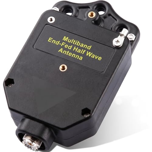
GOOZEEZOO 150 W end fed antenna transformer
A 49 to 1 transformer for an end fed. Pair it with a choke and a counterpoise for a quiet installation.
Check priceUnder $50

Fumei
Fumei 1:4 HF balun, 200 W
A 4 to 1 balun for a feedpoint that genuinely needs impedance transformation, which is a different job from choking.
Check priceUnder $50

AURSINC
NanoVNA H4 vector network analyzer
Measures the choke impedance across frequency so you know your winding actually does what the table says.
Check priceUnder $100
Common questions
Questions people ask about this
Why do I get RF burns from my microphone?
Common mode current is flowing on the outside of your coax braid, which makes the feedline part of the antenna and brings RF voltage to the equipment chassis in the shack. The cure is a common mode choke at the antenna feedpoint, not a heavier ground wire. Stop transmitting at full power until it is fixed, because the burns are real and the voltage is at the operating position.
Will a better ground fix RF in the shack?
Almost never. At HF a ground wire of any practical length is a quarter wave or so long, which makes it a resonant radiator rather than a drain. Adding wire changes the frequency at which the problem appears without removing the current. Safety grounding is essential for lightning and fault protection and is simply the wrong tool for this particular symptom.
What ferrite mix should I use for an HF choke?
Type 31 for general HF work from 1.8 to 30 MHz, because it has high loss across the whole range and produces over 1,000 ohms of common mode impedance with ten to twelve turns on an FT240 core. Type 43 is better above about 14 MHz and into VHF. Using the wrong mix produces a choke that works on one band and does very little on the others.
Where should the choke go, at the radio or at the antenna?
At the antenna feedpoint, because that is where common mode current gets onto the braid. A choke at the radio end stops it entering the equipment but leaves the whole feedline radiating and receiving noise. Many stations benefit from one at each end, with the feedpoint choke doing the real work and the entry point choke catching the remainder.
Can common mode current raise my noise floor?
Yes, and it is one of the most under-appreciated effects. The outside of the feedline is an antenna that runs past every switching supply, LED driver and network cable in the house on its way to the shack. Fitting a proper choke frequently drops the received noise floor by several decibels, which is often more noticeable than the improvement on transmit.
Keep going
Related on this site
Disclaimer Researched guidance for planning purposes, not professional engineering, electrical or legal advice. Antenna work, RF exposure, mast and tower work, grounding and battery handling all carry real risk that depends on your specific site and installation. Verify anything safety-critical against current FCC rules, the National Electrical Code and the manufacturer's own documentation, and hire a professional where the job calls for one. We research equipment from published specifications, regulatory documents and verified owner reviews rather than claiming hands-on testing we have not done.